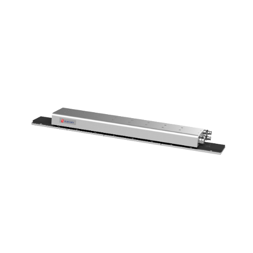
What is a linear motor?
A linear motor is a rotary motor "unrolled" flat. Instead of a rotor spinning inside a stator, a moving part travels along a straight track and pushes the load directly. No mechanical transmission converts rotation into linear travel. It has two parts:
A rotary motor needs a ball screw, belt or rack to move something in a line. A linear motor drives the load directly, which is where its dynamics come from.
How a linear motor works
Force from a moving magnetic field
Three-phase current in the coils creates a magnetic field that travels along the primary. That field pulls against the permanent magnets in the track, and the resulting force moves the primary along the axis. Reversing the current sequence reverses direction. Thrust follows current, so the drive controls force as well as position.
Commutation and feedback
The drive must know where the coils sit relative to the magnets so it can switch current in the right phase. This is commutation, and it relies on a linear encoder reading position along the track. Nothing mechanical holds the primary in place, so the axis always runs closed-loop on encoder feedback. The encoder and a servo drive are part of the system, not optional extras.
Typical performance ranges
Typical linear-motor CNC axes reach 1–5 g acceleration and 2–5 m/s travel speed. The exact figures depend on moving mass, thrust, drive power and guide quality, so check them against the datasheet of any specific model.
Types of linear motors
| Type | How it differs | Cogging | Thrust density | Magnetic attraction | Typical use |
|---|
| Flat, ironless | Coils in a non-magnetic body, running over a magnet track | None | Lower | Little to none | Smooth-motion stages, inspection |
| Flat, iron-core | Coils wound on a laminated iron core | Present; managed by design and control | Higher | Strong, often several times continuous thrust | CNC feed axes needing high force |
| U-channel | Forcer runs between two facing magnet rows | Typically none (ironless) | Moderate | Largely cancelled between the rows | Compact stages, light-to-medium axes |
| Tubular | Magnet rod with a coil that slides over it | Typically low | Moderate | Contained inside the tube | Short-stroke push-pull tasks |
| Induction | Conductive reaction plate instead of magnets | None | Typically lower | Varies with design | Long-travel transport, rarely precision machining |
Flat (platen) motors
Flat motors are the usual choice for machine tool axes. The ironless/iron-core split above is the main design decision: ironless gives smoother low-speed motion, iron-core gives more thrust for its size. Iron-core primaries pull hard on the magnet track, commonly cited as roughly 3–10× their continuous thrust depending on design. That load lands on the guide and bearings and must be sized for.
U-channel motors
The forcer sits between two magnet rows, which typically cancels most of the magnetic pull on the guide. These motors suit compact, lightly loaded axes.
Tubular motors
A tubular motor has a rod containing magnets and a coil that slides over it. It looks like an actuator, which is why "linear actuator" is used loosely for it.
Induction linear motors
An induction linear motor has no permanent magnets. The primary induces current in a conductive plate and pushes against it, so a long track costs less than a magnet row. Efficiency and force density are typically lower, so they appear mostly in long-travel transport rather than CNC feed axes.
Axis-integration checklist for CNC builders
The motor supplies thrust only. Use this list when laying out a linear-motor axis, then confirm each point against the datasheet of the model you pick.
| Item | What to settle | Why it matters |
|---|
| Thrust | Peak and continuous force against moving mass and cutting load | Sets acceleration and whether the axis stalls in a cut |
| Guide | Rail type, rating and stiffness, including the magnetic pull of an iron-core primary | The guide carries both the load and the attraction force. See rail load ratings before sizing |
| Linear encoder | Resolution, commonly 0.1–1 µm for incremental scales, finer with interpolation | Resolution is not accuracy, but it limits what the axis can position and how smooth low-speed motion is |
| Servo drive | Current rating, commutation setup, feedback type | Closes the loop and keeps thrust smooth |
| Cooling | Natural convection or liquid cooling, and where coil heat goes | Heat can reach the machine structure and drift the axis |
| Cables | Cable carrier rated for continuous flexing | Power and encoder cables move with the primary every stroke |
| Vertical axes | Brake or counterbalance | No screw holds the load when power drops |
| Debris | Covers or wipers over the magnet track | Swarf sticks to magnets |
Sizing an axis: a worked example
This is a generic sizing calculation; confirm the final figures with an application engineer against the motor datasheet. Take an axis with 60 kg of moving mass (table, workpiece, primary) that must accelerate at 2 g (about 19.6 m/s²):
Force to accelerate: 60 kg × 19.6 m/s² ≈ 1,180 N.
Add friction, cutting force and margin. Reaching roughly 2,000 N peak is realistic.
Check that thrust is available at the continuous rating for the duty cycle, not just at peak.
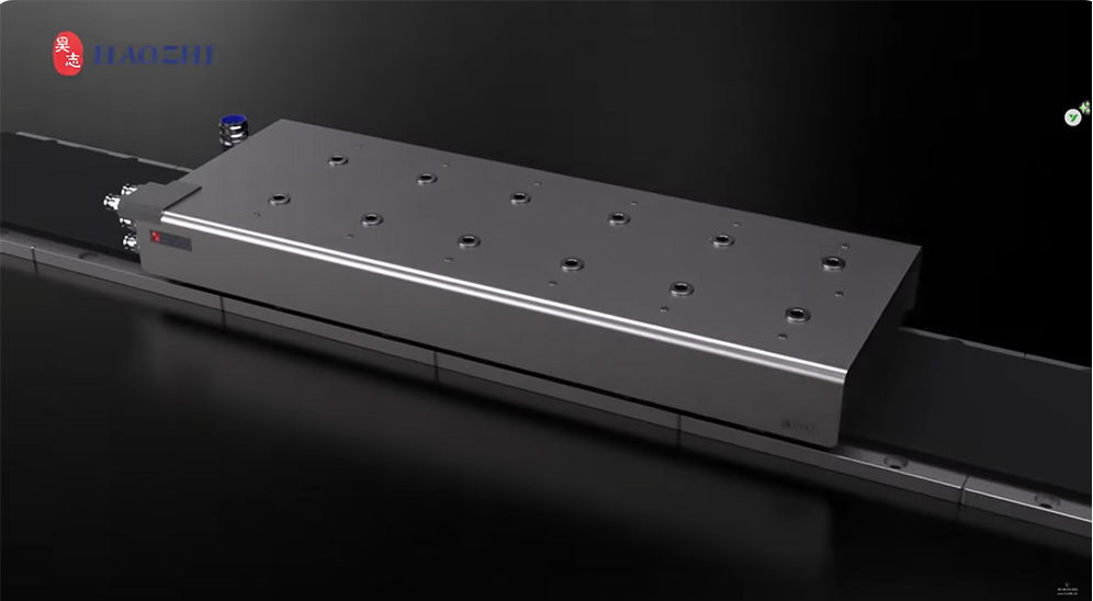
A motor in the 2,000 N class, such as the DLMF-03W 2,000 N flat linear motor, is the right order of magnitude for that load. Whether 2,000 N is peak or continuous, and which cooling it needs, must be confirmed on the product page. For heavier duty, the DLMF-04W high-thrust water-cooled linear motors address the heat that high thrust generates. The DLMF-01W compact flat linear motors suit lighter axes where space is tight. If you want a model matched to your own mass, stroke and acceleration, request a technical consultation.
Advantages and limitations
Advantages (typically)
No screw backlash, wear or windup, because there is no mechanical transmission.
High acceleration and speed, since the moving mass is small.
Accuracy is set mainly by the encoder and control loop.
Few wearing parts in the drive path.
Limitations
Higher system cost: encoder, drive and guide often add significantly to the motor price. The linear motor cost factors article breaks down what drives the total.
Coil heat needs managing.
Strong magnet attraction complicates handling, and debris can collect on the track.
No mechanical advantage, so all thrust must come from the motor.
Vertical axes need a brake or counterbalance.
Linear motor vs ball screw vs linear actuator
The decisive trade-off is holding force and cost versus dynamics. A ball screw holds a load without power and usually costs less, while a linear motor gives higher acceleration and a drive path with nothing to wear. The ball screw advantages and limitations article covers the screw side in depth.
| Drive method | Backlash / wear | Speed | Cost level | Typical use |
|---|
| Linear motor | No transmission to wear; encoder-limited | Typically high | Higher | High-dynamics CNC axes, stages |
| Ball screw | Preload manages backlash; screw wears over time | Limited by screw length and critical speed | Moderate | Long stroke, high-thrust axes |
| Electric linear actuator (screw- or belt-based) | Depends on internal mechanism | Typically moderate | Low to moderate | Packaging, lab equipment, general automation |
Choose the linear motor when acceleration and contact-free drive justify the extra cost and thermal work. Choose a screw when stroke is long, thrust is high or the axis must hold position unpowered.
Where linear motors are used
High-speed CNC feed axes
Semiconductor and inspection stages
Pick-and-place and automation lines
Maglev transport, the best-known large-scale example
Is a linear motor right for your machine?
Check these before choosing:
Acceleration: do you need dynamics a screw cannot deliver?
Stroke length: longer travel means more magnet track, which adds cost.
Accuracy target: it depends on encoder resolution and control quality, not the motor alone.
Thermal budget: can the structure tolerate coil heat, or does the axis need water cooling?
Vertical loading: if yes, plan a brake or counterbalance.
If most answers favor a linear motor, the next step is matching thrust, size and cooling to your axis layout. Browse linear motors and feed systems for CNC machines, or talk to our engineers about your axis. Rail and ball screw options for the same axis are listed under linear guides and ball screw systems.
Linear motor FAQ
What is a linear motor?
A linear motor is an electric motor laid out flat so it produces straight-line force directly. A coil unit (primary) interacts with a magnet track (secondary), so no screw, belt or gear is needed to turn rotation into linear travel. The load moves with the primary, and an encoder closes the position loop.
Does a linear motor need a guide or rail?
Yes. A linear motor creates thrust but does not support the load or hold the gap between coil and magnets, so the axis needs a linear rail or hydrostatic guideway. A linear guide only supports and directs a load, so it is not the same thing as a linear motor.
What is the difference between a linear motor and a linear actuator?
A linear actuator is usually a complete unit in which a rotary motor drives a screw or belt. A linear motor is the direct-drive thrust element alone, and the builder supplies the guide, encoder and drive. Some actuators use linear motors inside, which blurs the line.
Linear motor vs ball screw: which is better for a CNC machine?
It depends on the application. Linear motors suit high acceleration and smooth, wear-free drive. Ball screws suit long strokes, high thrust and holding loads without power, usually at lower cost. Compare both against your travel, dynamics, thermal limits and budget before deciding.
Do linear motors need cooling?
Often, yes. Coils generate heat that can transfer into the machine structure and affect accuracy. Lightly loaded axes may manage with natural convection, while demanding duty cycles typically use water-cooled motors or other thermal management to keep the axis stable during long runs.
Cost depends on thrust, stroke length, cooling and the encoder, drive and guide you add. The motor is only part of the axis budget, and longer strokes need more magnet track. The main drivers are explained under linear motor cost.

 Home