What Is a Mill Rotary Table, Exactly?
Four parts make up the basic design:
Base. A solid base clamps to the mill's table or to a fixture.
Table. A precision-machined disc carries the workpiece. T-slots on its face hold the clamps, and a through hole in the center usually accepts a Morse taper center or fixture.
Drive. A worm, turned by a handwheel, meshes with a worm wheel that forms part of the table.
Scale. A graduated dial, usually with a vernier, shows the angle. A typical dial reads 1 arc-minute per division, and the vernier refines that to about 10 arc-seconds (some read 5). The exact figure is on each model's datasheet.
The worm-to-table ratio is commonly 40:1, 72:1 or 90:1, though other ratios exist. A ratio is practical when it divides evenly into 360°. At 90:1, one handwheel turn moves the table 4°. At 72:1 it moves 5°, and at 40:1 it moves 9°.
A dividing head is a different tool, although some rotary tables accept the same index plates. It holds work on a spindle nose, in a chuck or between centers with a tailstock, and indexes through plates of hole circles. A universal dividing head also tilts from horizontal to vertical. It steps from position to position, so it is rarely used for continuous rotary milling. The exception is helical work, where a gear train links it to the feed screw. With a 40:1 head, five equal divisions means 72° each, which is 8 crank turns.
What Is the Purpose of a Rotary Table?
A rotary table lets a mill machine features arranged around a center, which a straight-line mill table can't do alone. Typical jobs include:
drilling or cutting at exact intervals, such as bolt circles and flange hole patterns;
milling arcs, radii and circular or semicircular contours;
rotary contouring, the "turning on a mill" approach, where the table spins the part against a stationary cutter;
adding a fourth axis when the table is powered and driven by the machine's CNC control.
What Are the Two Main Types of Rotary Tables?
The main split is manual (a hand-cranked worm drive) versus powered (motor-driven and CNC-controlled).
Manual vs. powered (CNC) tables
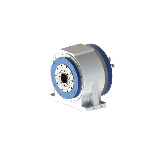
On a manual table, the operator turns the handwheel, reads the dial and indexes by hand. That suits one-off parts and simple hole patterns. A powered table moves to programmed angles and can rotate continuously while the mill cuts, which a manual table can't do practically. The trade-off is that the control must be able to drive an extra axis. Direct-drive designs like a Ø255 mm high-torque CNC rotary table are built for this work. More powered options sit in the range of CNC rotary tables and 5-axis milling heads.
Horizontal vs. vertical mounting
Tables are also split by orientation. Mounted flat, the table rotates about a vertical axis, in line with a vertical mill's spindle. Mounted on its end, or flat on a 90° angle plate, it rotates about a horizontal axis, where a tailstock can support the work between centers.
Worm Drive vs. Direct Drive: Retrofit Numbers
When you power a table for a fourth axis, the drive style sets torque, speed and what the encoder actually measures. The worm column below is an illustrative calculation, not a product: a 3,000 rpm, 2 Nm servo on a 90:1 worm at roughly 35% efficiency. Worm efficiency varies by design. The direct-drive column uses figures from Haozhi catalog model titles.
| Powered worm table (illustrative) | Direct-drive table (catalog examples) |
|---|
| Torque at the table | About 63 Nm (2 Nm × 90 × 0.35) | Up to 748 Nm peak (DZDH-255) |
| Max speed | About 33 rpm (3,000 ÷ 90) | 1,000 rpm (DZDV-630, DZGD-200A10); 1,400 rpm (DZDV-500 high-speed) |
| Encoder | 20-bit motor encoder: about 94 million counts per table turn, ≈0.014 arc-sec | 27-bit encoder (DZDV-465-A4, Siemens): about 134 million counts per turn, ≈0.010 arc-sec. The A3 uses a 28-bit encoder |
| Encoder location | On the motor shaft, so worm mesh error and backlash sit outside the loop | On the table, so it measures the actual table angle |
| Load examples | Set by the table casting and worm | 500 kg (DZDV-465-A3); 600 kg (DZDV-500 high-torque) |
Resolution is nearly identical, so it isn't what separates the two. A fine encoder on the motor still can't see the worm's tooth error or backlash. A table-mounted encoder can. Resolution also isn't accuracy, so compare the datasheet's stated positioning accuracy and repeatability for any specific table. Peak torque is not continuous torque either.
For a retrofit, check three things. First, the encoder interface the table uses against what your control accepts. Haozhi's range includes a 27-bit Siemens-encoder table and BiSS-C models. Second, the drive and control must support a fourth axis. Third, plan for cable and coolant routing. For heavy cuts, a 748 Nm peak-torque table is the kind of option to price against a worm-driven unit.
How a Rotary Table Works on a Mill
Clamp the table to the mill table, with its base edge or a T-slot roughly parallel to X.
Indicate the table. Sweep its face with a dial test indicator and align an edge to the X axis.
Center it. Mount the indicator in the spindle, sweep the center bore, and adjust X and Y until the needle holds steady. Zero X and Y there.
Center the workpiece. Clamp the part, then sweep it with the same spindle-mounted indicator.
Swap in the cutter. Remove the indicator and fit the tool. Use a BT-ER holder on a BT-taper spindle or an ISO-ER holder on an ISO-taper one. An ER collet then grips the drill or end mill.
Offset and index. Move X by the cutting radius, then rotate and cut.
Worked example: six holes on a 100 mm bolt circle, 90:1 table. Offset X by 50 mm, the circle's radius, from the zeroed center. Holes sit 360° ÷ 6 = 60° apart. At 4° per handwheel turn, that is 15 turns between holes. Lock the table, drill, release the lock, turn 15 times, lock it again and drill the next hole. Always approach each position from the same direction so backlash does not enter the count. A powered table simply runs the program at 0°, 60°, 120°, 180°, 240° and 300°.
How to Choose a Rotary Table
Use a manual table for occasional indexing, and move to a powered table for programmed, repeatable work. Check these first:
Table diameter and centerline height. Both must fit the workpiece and the mill's envelope.
Workpiece weight. The table's load rating must exceed it with margin.
Worm ratio (manual tables). It sets the angle per handwheel turn.
Drive style. Worm drive gives torque multiplication and lower cost. Direct drive gives speed and encoder feedback at the table.
Control capability. The mill's control must be able to drive a fourth axis.
Tilting as well as rotating takes you into 5-axis territory. A head such as the DBDB-335 18,000 rpm high-rigidity milling head suits those setups. If you are matching a table to a specific machine layout, send us the details.
FAQ
What are the two main types of rotary tables?
Manual tables use a handwheel and worm gear, and the operator indexes by hand. Powered tables use a motor under CNC or controller command, either through a worm or direct drive. Tables are also described as horizontal or vertical, which describes mounting orientation rather than drive.
What is the purpose of a rotary table?
It positions a workpiece at precise angles so a machine can drill hole patterns, mill arcs and radii, and cut contours around a center. Powered and run from the CNC control, it also gives a mill a fourth axis for continuous rotary machining.
What is a table in a milling machine?
It is the work-holding surface that carries the part under the cutter, usually moving along X and Y. A rotary table is an add-on that sits on it and adds rotation, so the part can be turned as well as traversed.
What is the best table top milling machine?
No single machine is best; size the mill to the rotary table. Benchtop mills often offer about 10–12 in (250–300 mm) from spindle to table. A 6 in rotary standing roughly 4 in tall, plus a 3 in part and a 4 in drill and holder, uses about 11 in. Also check the table load rating against rotary weight plus the part.
Ready to match a powered table to your machine? Talk to our engineers.

 Home