By the Haozhi technical content team, Guangzhou Haozhi Industrial Co., Ltd.
What Is a Ball Screw?
A ball screw is a feed-drive assembly. A screw shaft with a helical groove, a ball nut with a matching groove, and a set of steel balls rolling between them make up the assembly. Turn the shaft and the nut travels along it. Hold the shaft still and turn the nut, and the shaft moves instead.
Anatomy at a glance
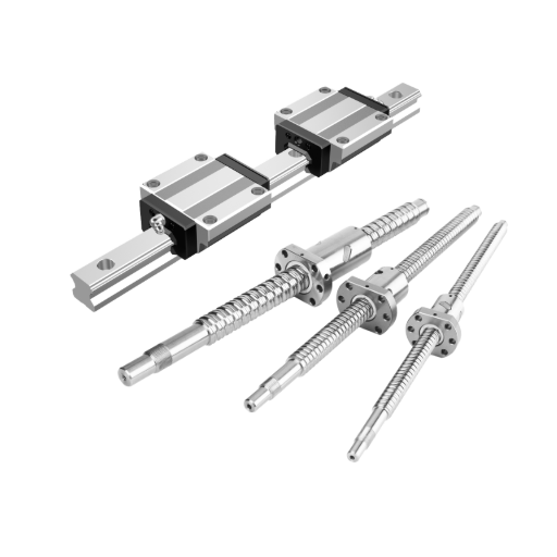
A ball screw assembly is made of the following parts, from the shaft outward:
| Label | Part | Where it sits | What it does |
|---|
| 1 | Screw shaft | Runs the full travel length | Hardened shaft with a precisely formed helical raceway, either ground or rolled |
| 2 | Balls | Inside the raceway between shaft and nut | Carry the load by rolling instead of sliding |
| 3 | Ball nut | Rides on the shaft | Housing with a matching raceway, usually with a flange or threaded body for mounting |
| 4 | Return path | Tube, end cap or insert on the nut | Carries balls from one end of their loop back to the other, so the nut can run the full shaft length |
| 5 | End supports | Bearings at one or both shaft ends | Take axial load and fix the shaft position |
How Does a Ball Screw Work?
In a sliding screw, thread flanks rub against each other. In a ball screw, the balls roll in the raceway and re-enter the nut through the return path. Less friction means less heat and less drive torque.
Published figures show the gap. Anaheim Automation states that current recirculating ball screws typically exceed 90% efficiency. THK's catalog torque example uses η = 0.96 for a ball screw against η = 0.32 for a sliding screw with a 0.2 friction coefficient, and THK puts the required drive torque at about one third of a sliding screw's.
Because rolling friction is low, a ball screw can usually be back-driven. THK notes that this lets it convert straight motion into rotation as well as the reverse. On vertical axes, a brake or holding motor is normally added for that reason.
The one relationship worth remembering is:
Drive torque ≈ thrust × lead ÷ (2π × efficiency)
For example, 2,000 N of thrust through a 0.010 m lead at 90% efficiency needs about 2,000 × 0.010 ÷ (2π × 0.9) ≈ 3.5 N·m at the shaft, before bearing and seal friction. That low torque for a given thrust is why ball screws appear wherever positioning must be precise and repeatable.
What Is a Ball Screw Used For?
A ball screw is used where a machine needs efficient, accurate linear positioning and force transmission under load. It turns a motor's rotation into controlled travel and holds position well under changing loads.
Machine tools and CNC feed axes
This is the most common use. Mills, lathes, routers and machining centers use ball screws on X, Y and Z axes, where positioning accuracy and axial rigidity directly affect part quality. The screw sits between a servo motor and the moving table or saddle, while a linear guide carries the load.
Automation, positioning stages and robotics
Pick-and-place units, cobot linear axes and motorized stages use ball screws for smooth, repeatable moves. A common arrangement has the nut driving a carriage that rides on a linear guide.
Semiconductor, medical, inspection and test equipment
These systems need small, repeatable steps and little stick-slip. Rolling contact allows fine incremental motion without the jerkiness of sliding friction.
Heavy-load uses
Presses, injection molding machines and aerospace actuators sit at the top of the load range. Thomson classes any ball screw assembly above 20,000 lbf (89 kN) as high load, against 1,350–20,000 lbf (6–89 kN) for mid load and up to 1,350 lbf (6 kN) for miniature and low load. Anaheim Automation's TBI Motion line runs from 4 mm to 80 mm in shaft diameter, with dynamic loads up to 7,240 kgf (about 71 kN). Larger shaft diameters and more balls spread the load over more contact points. These are other manufacturers' published catalog figures, so use them as a sense of scale and read the rating on your own part's drawing.
Ball screws are not right for everything. They are often quoted at roughly 2–4 times the cost of a comparable lead screw. They also back-drive under load, so vertical axes need a brake, and they need wipers or bellows in chip-heavy environments. The ball screw pros and cons set these against the gains in efficiency, rigidity and precision.
Ball Screw Specs Explained: Lead, Pitch, Accuracy and Preload
How to determine the pitch (and lead) of a ball screw
On a single-start screw the two are equal, which is why people use the words interchangeably. A multi-start screw has a lead that is a multiple of its pitch, so check which one a catalog quotes.
To choose lead, work backwards from speed:
Lead = required linear speed ÷ screw rpm
If the axis needs a 24 m/min rapid and the motor tops out at 2,400 rpm, lead = 24,000 mm/min ÷ 2,400 rpm = 10 mm. At the long end, THK lists a large-lead rolled screw (30 mm shaft, 60 mm lead) running 2 m/s at 2,000 rpm.
Lead trades three things against each other:
Speed: a longer lead gives more travel per revolution, so a given rpm moves the axis faster.
Resolution: a shorter lead gives finer steps. A 10 mm lead with a 10,000-count encoder gives 0.001 mm per count.
Torque: a longer lead needs more torque for the same thrust, as the formula above shows.
How accurate are ball screws?
Accuracy depends first on how the shaft is made. Ground screws are more precise than rolled screws. Accuracy is graded by lead error over a stated travel distance, and lower grade numbers mean tighter tolerance. The JIS B 1192 grade tables give travel-distance error per 300 mm of about:
Manufacturer catalogs show the same split. Thomson lists precision rolled assemblies at ±0.004 in per ft (23 µm per 300 mm) and ground assemblies at ±0.0005 in per ft. THK's measurement sheet for a ground BIF3205 screw gives a ±0.011 mm representative travel error as the standard value. ISO classes follow the same logic with their own tolerance tables, so read the exact grade and test distance on the supplier's drawing.
The screw's grade is not the accuracy of the axis. Mounting alignment, bearing preload, thermal growth of the shaft, backlash and the position feedback (rotary or linear encoder) all add error. A high-grade screw on a poorly mounted axis will not hold its rated precision.
Preload and backlash
Backlash is the small axial play between nut and shaft that shows up as lost motion when direction reverses. Preload removes it by loading the balls against the raceway, either with oversize balls or with two nuts pushed against each other.
The trade-off: preload raises axial rigidity and removes play, but it also adds friction, heat and wear. Light preload suits moderate accuracy needs. Heavier preload belongs on axes that need stiffness against cutting forces, and it needs better lubrication and cooling.
Other numbers to check
Shaft diameter: drives load capacity and stiffness, and sets critical speed.
Dynamic and static load ratings: used to calculate service life against your duty cycle.
Critical speed: the rpm at which the shaft starts to whip. It falls as the unsupported length grows.
Travel and shaft length: longer shafts sag and flex more, so rigidity and critical speed both suffer.
Worked example: sizing a CNC axis, checking life, critical speed and buckling
Take a horizontal machining-center axis with a 400 kg moving mass, a 25 mm shaft with a 10 mm lead, 1,000 mm between supports, and a 24 m/min rapid. The dynamic load rating Ca of 14 kN and the 21.5 mm root diameter below are illustrative figures. Use the values on your chosen model's drawing.
Speed: 24,000 mm/min ÷ 10 mm = 2,400 rpm at rapid.
Friction load: guide friction coefficient 0.005 × 400 kg × 9.81 ≈ 20 N.
Load spectrum by share of revolutions: 50% rapid at 20 N, 30% light cut at 820 N, 20% heavy cut at 2,020 N (2,000 N cutting force plus friction).
Equivalent load: Fm = (0.5 × 20³ + 0.3 × 820³ + 0.2 × 2,020³)^(1/3) ≈ 1,220 N.
L10 life in revolutions: (Ca ÷ Fm)³ × 10⁶ = (14,000 ÷ 1,220)³ × 10⁶ ≈ 1.5 × 10⁹ revolutions.
Life in hours: at an average 600 rpm (36,000 revolutions per hour), that is about 42,000 hours.
Peak torque: 2,020 N × 0.010 m ÷ (2π × 0.9) ≈ 3.6 N·m, which sets the minimum servo motor torque before acceleration.
Critical speed: the form used in many manufacturer catalogs is N_c = f × 10⁷ × d_r ÷ L², with root diameter d_r and unsupported length L in mm. The factor f depends on the end supports: 3.4 fixed–free, 9.7 supported–supported, 15.1 fixed–supported and 21.9 fixed–fixed. For a fixed–floating layout (fixed–supported), N_c = 15.1 × 10⁷ × 21.5 ÷ 1,000² ≈ 3,250 rpm. Keeping operation to 80% of that gives an allowable 2,600 rpm, so the 2,400 rpm rapid passes with little margin. A longer shaft or higher rpm would fail it, and the fix is a larger diameter or a fixed–fixed arrangement.
Buckling: the Euler limit is P = n × π² × E × I ÷ L², where E = 206,000 N/mm², I = π × d_r⁴ ÷ 64 ≈ 10,500 mm⁴, and the end-support factor n is 0.25 fixed–free, 1 supported–supported, 2 fixed–supported and 4 fixed–fixed. With n = 2, P ≈ 2 × π² × 206,000 × 10,500 ÷ 1,000² ≈ 42,600 N. A safety factor of 2 leaves about 21 kN allowable against the 2,020 N peak, so buckling does not govern this axis. It often does on long, slender screws in compression.
L10 is the life that 90% of identical screws reach or exceed under these conditions. Contamination, lubrication and misalignment usually shorten real service life well before the calculated figure.
How to Set Up and Choose a Ball Screw
Setting up a ball screw
Follow the manufacturer's installation manual for your exact part. In general, the sequence is:
Choose the end-support arrangement. Fixed–fixed gives the highest rigidity and critical speed but needs careful alignment and thermal allowance. Fixed–floating is the usual compromise. Fixed–free suits short, light axes.
Mount and align the supports. Shaft and bearing misalignment is a leading cause of early wear. Check that the shaft axis runs parallel to the guide axis along the whole travel.
Keep the nut on the shaft. If you must remove the nut, use the supplied sleeve, because the balls fall out when the nut leaves the shaft.
Lubricate before the first run with the grease or oil the manufacturer specifies.
Run at low speed first. Listen for noise and feel for heat before ramping up.
Stay inside the limits. Do not exceed critical speed, buckling load, rated axial load or travel stops.
Installation errors are cheaper to catch in step 5 than after a crash or a worn raceway. For a second opinion on an axis layout, talk to Haozhi's engineers.
Quick selection checklist
| Question | What to decide | Why it matters |
|---|
| How much load? | Peak axial load, plus vertical or horizontal orientation | Sets shaft diameter and load rating |
| How far and how fast? | Travel length, max speed, acceleration | Sets lead, critical speed and shaft length limits |
| How accurate? | Ground or rolled, accuracy grade, encoder type | Sets achievable positioning and cost |
| How stiff? | Preload level, end-support type | Controls deflection under cutting or inertia loads |
| How is it mounted? | Nut style, supports, motor coupling | Affects alignment and installation effort |
| Where does it run? | Contamination, coolant, temperature | Decides seals, lubrication and thermal allowance |
Once load, speed, travel and accuracy are fixed, the range narrows quickly. Haozhi's precision ball screws for CNC motion control are the next step for catalog selection, and the linear guide and ball screw systems overview shows how the parts fit together. To match a screw to a specific machine layout, request technical consultation.
Ball Screw vs Linear Guide
The two parts do different jobs. The ball screw drives the motion: it converts motor rotation into thrust and sets position. The linear guide supports the load and constrains the carriage to a straight path. They normally work as a pair, with the nut pulling a carriage that rides on guide blocks.
Guides come in two main rolling-element types. Heavy-duty ball linear guides carry load on recirculating balls, which suits smooth, fast axes. Heavy-duty roller linear guideways use line contact between roller and rail, which generally gives higher stiffness for heavy or shock-loaded axes. Guide size, block count and preload are chosen with the same load and accuracy numbers used for the screw, and the linear rail guide walks through that selection.
FAQ
How do I set up a ball screw?
Pick the end-support arrangement first, because it fixes your critical speed and buckling limits. Align the supports so the shaft runs parallel to the guide, keep the nut on its sleeve, and run at low speed before full travel.
How to determine the pitch of a ball screw?
Measure the distance between adjacent thread crests for pitch, then check the number of starts, since lead equals pitch × starts. For selection, divide the required linear speed by motor rpm. A 24 m/min rapid at 2,400 rpm needs a 10 mm lead.
What is a ball screw used for?
It positions and pushes loads along a straight line with little friction loss. Typical homes are CNC feed axes, automation stages, semiconductor and inspection equipment, and presses.
How accurate are ball screws?
Thomson lists ground assemblies at ±0.0005 in per ft against ±0.004 in per ft for precision rolled, roughly an eightfold gap. Check the grade and test distance on the drawing, because vendors define the measurement conditions differently.
What is a ball screw?
It is a threaded shaft and matching nut that roll against each other on recirculating steel balls. THK puts its drive torque at about one third of a sliding screw's.
Ball screw vs lead screw: what's the difference?
THK's example puts a sliding screw at η = 0.32 against 0.96 for a ball screw, but lead screws cost less and tend to self-lock. That self-locking is why a lead screw can hold a vertical load without a brake.
Do ball screws need lubrication and maintenance?
Yes, with the grease or oil the manufacturer specifies, applied before first use and repeated on a schedule. Wipers or bellows keep chips and coolant out, and rising noise, heat or backlash signals wear.
Can a ball screw back-drive?
Usually, because a load on the nut can spin the shaft when motor power is cut. Vertical axes therefore use a motor brake, and steeper leads make the effect stronger.
Ball screw sizing formulas
First-pass sizing uses five relationships: lead = speed ÷ rpm, torque = thrust × lead ÷ (2π × η), L10 = (Ca ÷ Fm)³ × 10⁶ revolutions, N_c = f × 10⁷ × d_r ÷ L², and Euler buckling P = n × π² × E × I ÷ L². Dimensions, load ratings and grades vary by model, so take them from the supplier's drawing.

 Home